PDQ - M5, 360, 360+, Tandem, Surfline
Prerequisites and Tools needed
Step 1 – Disconnecting Power
Step 2 – Getting the Activation Node Ready
Step 3 – Powering the Sealevel
Step 4 – Wiring Sealevel Inputs
Step 4a – Wiring 360+ or Surfline Inputs
Step 4b – Wiring M5, 360, or Tandem Inputs
Step 5 – Wiring Sealevel Outputs
Step 6 – Finalizing Sealevel
Logging into PDQ software
Changing Activation Node settings – 360, 360+, Tandem, Surfline
Changing Activation Node settings – M5
Programming the 360+ or Surfline
Prerequisites
• Cat6/Cat5e wiring available at PDQ Activation Node from Network Rack
• Access to PDQ machine interface
• Access to PDQ pump station and activation node
• Access to the Bay Node (M5, Tandem, 360)
• Knowledge how to use Wago terminals
• Laserwash 360+ MUST be running software 1.2.0 or later.
• Surfline MUST be running software 0.9.7.2 or later.
Tools
• Small flathead screwdriver
• Wire strippers
• Wire cutters
• Laptop with ethernet port
• Zip ties
• Multimeter
Step 1 – Disconnect Power
Locate PDQ pump stand. Shown is a Laserwash 360+ pump stand, Laserwash 360 is similar. Use the included allen wrench to open the JO box.
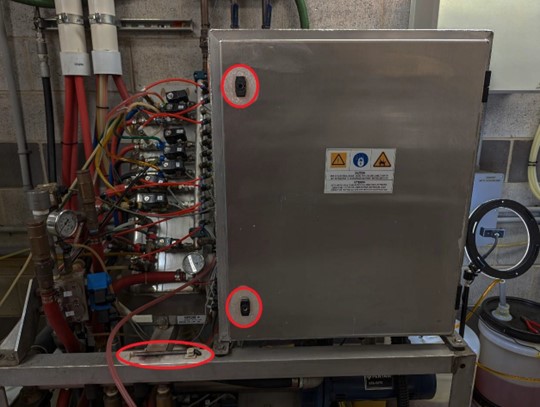
Laserwash M5 and Surfline JO box is located on the wall near the pump stand.
Tandem uses a separate 2 pole breaker for its 24vac transformer in the building circuit panel.
With the JO box open, locate the two pole breaker.
|
|
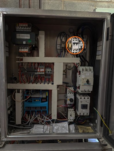
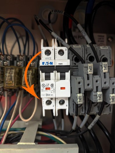
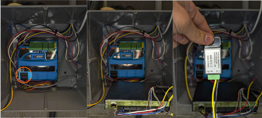
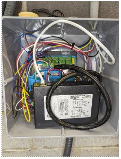
Step 2 – Activation ProvisionOpen the activation node box and verify the activation node is off. Use a multimeter and test between points A and B for 24vac. If points are still live with AC voltage, check that the correct 2 pole breaker was turned off. With power removed from the activation node, document placement of, then remove all wires from the output card (highlighted) EXCEPT “Output Power” wires. Then remove wires from the Green or Grey input TB2 terminals (top of the activation node). Zip tie or cut wires and store away from the node in a clean fashion. Ensure no stray copper strands could cause a short circuit. |
|
Step 3 – SeaLevel Power
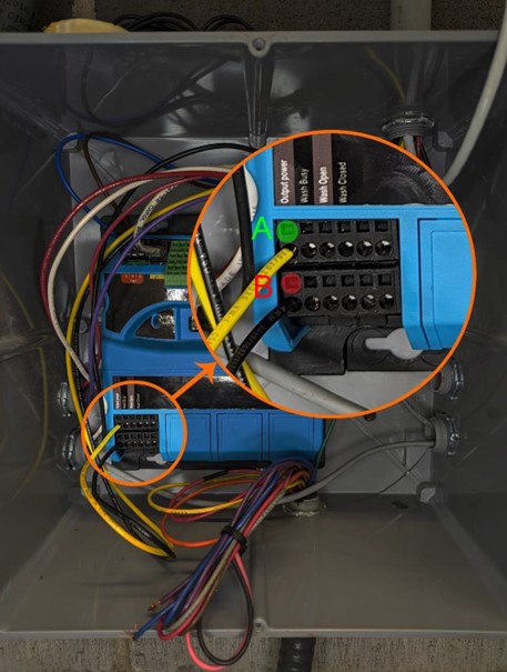
Remove “Output Power” wires from the output card. Acquire the correct SeaLevel for the bay you’re working on and insert the “Output Power” wires into the “AC IN” terminals of the green AC/DC transformer.
Step 4 – Wiring SeaLevel Inputs
Use a strand of wire to connect TB2 1A to Output Card “Output Power” 1A.
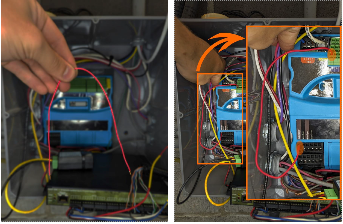
Connect “Wash Status (Busy)” red wire to Output Card 2a “Wash Busy.” Connect “Input Common” black wire to Input TB2 1C.
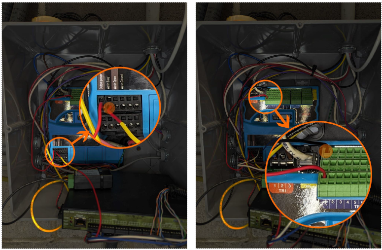
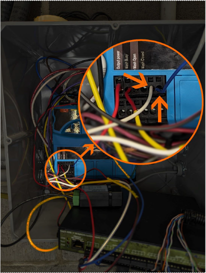
Step 4a – Laserwash 360+ and Surfline ONLY
Connect “Paystation Reset” white wire to Output Card 5a.
Connect “LPR Signal” blue wire to Output Card 6a.
Step 4b – Laserwash 360, Tandem, and M5
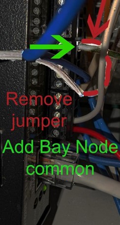
These machines do not have Custom Logic programming so the door eye signals must be captured from the Bay Node. The “Paystation reset” white and “LPR Capture” blue wires may need extended to reach the correct terminals on the Bay Node. ADD a common wire from the Bay Node TB2 6c to Sealevel C on terminal block 5 through 8. REMOVE the jumper between Sealevel terminal block 1 through 4 c and 5 through 8 c. LEAVE Activation
Node common attached to Sealevel terminal block 1 through 4 c.
LASERWASH M5 Bay Node is often located in the bay within the upper rear right or left box (attached to the festoon cable). LASERWASH 360 and TANDEM bay node is often located near the Activation Node in the pump room. Locations vary by installer. |
|
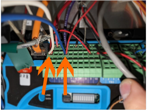
Double tap Bay Node TB2 1b for Entrance Door Eye trigger.
Double tap Bay Node TB2 4b for Exit Door Eye trigger.
In this example, the LPR camera is located in the bay and uses the Exit Door Eye trigger. If your LPR is located at the entrance, OMIT the white wire from your install. Use the blue wire at Bay Node TB2 1b. Within CMP, change
Devices>(your device)>Sealevel>Driver Output from 2 or 6 to 5. DO NOT TRIPLE TAP ANY TB2 TERMINAL.
Step 5 – Wiring Sealevel Outputs
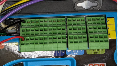
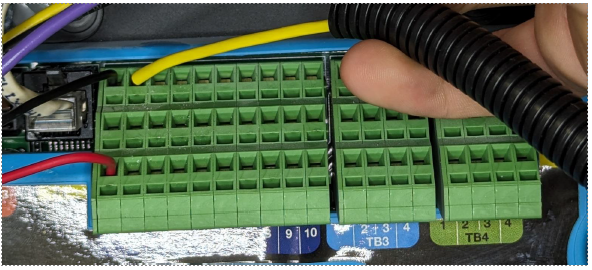
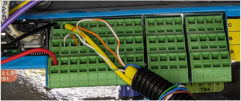
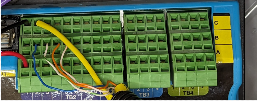
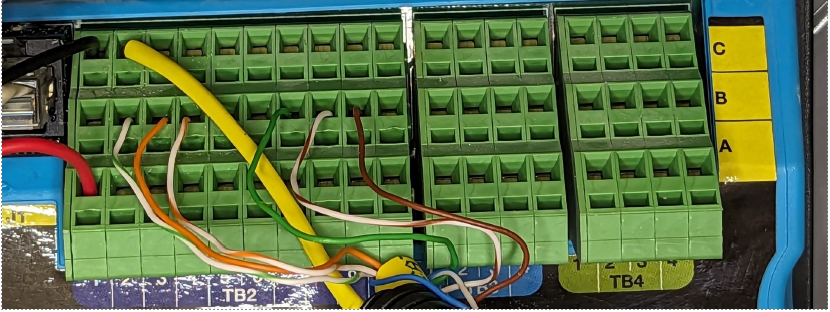
Your Activation Node TB2 terminal block should look as shown:
Attach the black Output Common wire to TB2 2c. In this image the yellow label obscures the black insulation of the wire.
For 3 washes with no add ons:
White/green > 2b > Package 1
Orange > 3b > Package 2
White > orange 4b > Package 3
For 4 washes with no add ons:
Blue > 2b > Package 1
White/green > 3b > Package 2
Orange > 4b > Package 3
White/orange > 5b > Package 4
For 3 washes with add ons:
White/green > 2b > Package 1
Orange > 3b > Package 2
White/orange > 4b > Package 3
Green > 7b > Package 5
White/Brown > 8b > Package 6
Brown > 9b > Package 7
For 4 washes with add ons:
Blue > 2b > Package 1
White/green > 3b > Package 2
Orange > 4b > Package 3
White/orange > 5b > Package 4
White/blue > 7b > Package 5
Green > 8b > Package 6
White/brown > 9b > Package 7
Brown > 10b > Package 8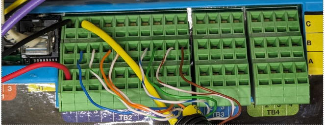
Step 6 – Finalizing Sealevel
Flip 24VAC breaker on. Allow machine to boot for approximately 3 to 5 minutes.
• Check that the Activation node lights are on and that there are no red flashing lights.
• Check that the Sealevel Stat light is on.
• Check that the Sealevel Com light is flashing.
• Restart Services on the kiosk and check that the appropriate Sealevel indicators are lit within Control Console.
Attach the Sealevel to a safe location within the Activation node box. Some boxes are too small for the Sealevel to be attached to the box such as this example. The Sealevel is flipped upwards and the box cover is reinstalled.
Logging into the PDQ web interface
Connect your laptop to the same subnet used for the PDQ machines. On the network rack, a free port consecutive to the ports used by the Dencar installation will work.
NOTE: In rare instances the PDQ machine is not connected to the network. If this is the case, the machine must be connected to the network and updated to the latest software release by the machine distributor.
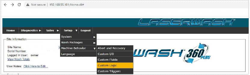
Using Google Chrome or FireFox, navigate to http://192.168.55.101 for bay 1. Bay 2 is http://192.168.55.102. Bay 3 is http://192.168.55.103. And so on.
The default username is “owner” and password is “12345”. You MUST log in with an account with owner level credentials.
Changing Activation Node settings
360, 360+, Tandem, Surfline
1. Navigate to Setup>System>Activation Unit
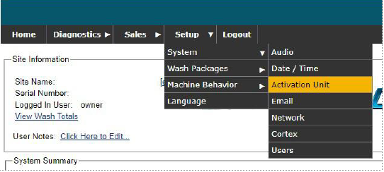
2. Ensure settings match as shown: 3. Once done, click “Submit” 4. Navigate to Diagnostics > Remote Control 5. Next to “New Command” type “test90” then click “Send.” Allow the conductor 3 to 5 minutes to restart. Note: The Wash Busy signal is inverted so that during a power outage the kiosk will go out of service. Note: You can change wash packages under Setup > Wash Packages > Set Active Packages |
|
M5
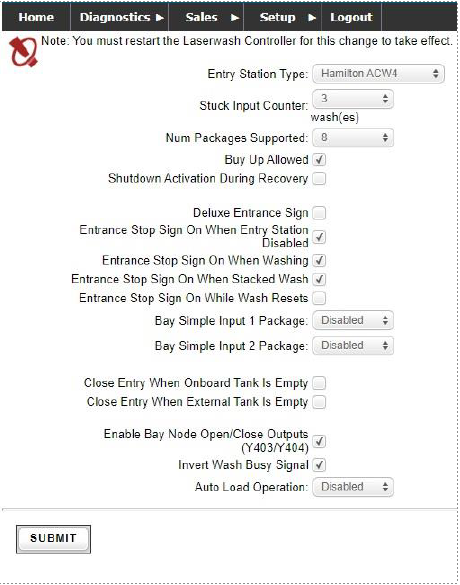
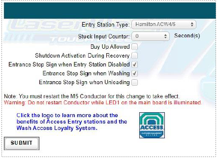
1. Navigate to Setup > Site Setup > Activation Setup 2. Ensure your settings match as shown: 3. Click “Submit” 4. Click “Home” at the bottom of the page. 5. Navigate to Diagnostics > Issue Manual Commands 6. Next to “New Command” type in “test90” then click “Send” 7. Allow the machine 3 to 5 minutes to reboot. |
|
1. Check the Software version by navigating to Diagnostics > About. The 5th line down shows the software version. Software version must be greater than 1.2.0.
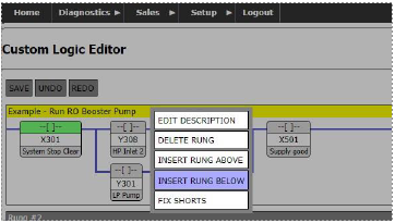
2. Navigate to Setup > Machine Behavior > Custom Logic
3. Click on the header that says “Example – Run RO Booster Pump” then click
“Insert Rung Below”
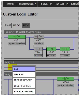
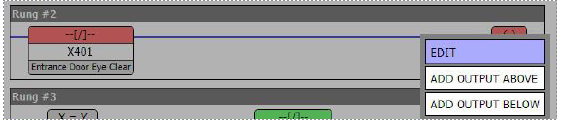
4. Click on the leftmost red dash on the blue line then click “Edit”
Match your settings to those shown:
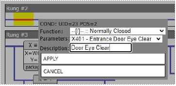
***If the bay does not have entrance photo eyes (typically when there is no door), use relay 402 which is the under chassis photo eye instead of 401.
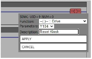
6. Click on the () box at the far right then click “Edit”
7. Match your settings to those shown:
8. Click on Rung #2 header then click
“Insert Rung Below.”
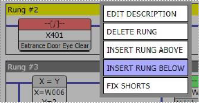
FOR EXIT MOUNTED LPR CAMERA ONLY
Repeat steps 4 through 7 for Rung #3, replacing X401 with X404 for Exit Door eye clear and replacing
Y104 for Y105 to Trigger LPR camera. (Only if you have exit door photo eyes)
10. FOR ENTRANCE MOUNTED LPR CAMERA ONLY Repeat steps 4
through 7 for Rung #3, replacing Y104 for Y105 to Trigger LPR camera.