Wash World High Velocity
pay station interface
Sealevel I/O wiring interface
INPUTS | TERMINAL | FROM HIGH VELOCITY |
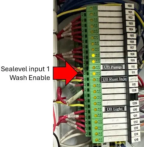
1 – Wash Status
| 1 | 1111 Wash Enable |
2 – Gate loop signal (if used)
| 2 | |
3 – Out of Service
| 3 | n/a |
4 – n/a
| 4 | |
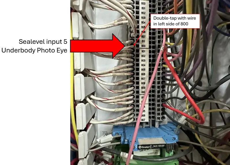
5 – Photo Eye
| 5 | 800 Underbody Photo Eye |
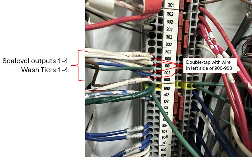
OUTPUTS | TERMINAL | TO HIGH VELOCITY |
1 | 1 N.O. | 900 |
2 | 2 N.O. | 901 |
3 | 3 N.O. | 902 |
4 | 4 N.O. | 903 |
5 | 5 N.O. | n/a |
6 | 6 N.O. | n/a |
7 | 7 N.O. | n/a |
8 | 8 N.O. | n/a |
Notes:
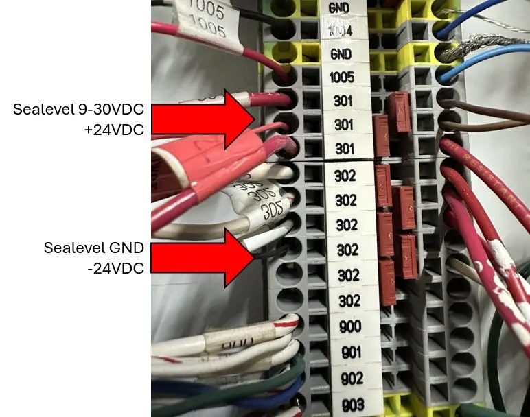
301 = +24VDC – connect to 9-30VDC on left side of Sealevel
302 = -24VDC – connect to GND on left side of Sealevel
1) On the Sealevel, connect the left side GND (-24VDC) to the input block 1 common on the front of the Sealevel. If there is a jumper from the Input block 1 common to the input block 2 common, remove the jumper.
2) On the Sealevel, connect the same -24VDC to the Sealevel output block common so all output blocks have a -24VDC common.
3) On the Sealevel, connect a +24VDC to the input block 2 common.
4) Wire per chart above or as follows:
-Connect input 1 on the Sealevel to the left side of UCC 1111 (Wash Enable)
-Connect input 5 on the Sealevel to the left side of UCC 800 (Underbody Photo Eye)
-Connect the output 1 on the Sealevel to the UCC 900 (Wash Tier 1)
-Connect the output 2 on the Sealevel to the UCC 901 (Wash Tier 2)
-Connect the output 3 on the Sealevel to the UCC 902 (Wash Tier 3)
-Connect the output 4 on the Sealevel to the UCC 903 (Wash Tier 4)
In the Dencar Customer Management Portal, Sealevel component settings:
-Invert inputs 1 and 5
-Set Pay Station Reset input to 5
-Set Pay station Reset pre/post to pre
-Set LPR Trigger input to 5
-Set LPR pre or post Trigger to post
-Set LPR Delay (seconds) to 4 (adjust if needed)
-Set Wire Type to 1
-Set Queue Control to 1
Wash Enable
Underbody Photo Eye
Wash Tiers