Activation Modules
(a.k.a. Wired/WIFI Relays, vac relays, self-serve relays, etc.)
Activating ancillary equipment such as Vacuums, Self-Serve, Tire Air Machines, Vending, etc.
There are 4 critical components related to a WIFI/Wired Relay installation. They are: 1) Network hardware 2) Site Controller (WIFI/Wired Relay Controller) 3) WIFI/Wired Relays 4) iPhone or Android phone app.
**For Self Serve applications Dencar requires a hard wired ethernet connection ran from the network to the relay**
When you take the Site Controller out of the box, please plug the screen emulator plug into the HDMI
port.
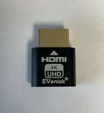
A screen emulator plug is used
instead of a full monitor. This plug
must be installed so that remote
support can be provided.
Plug the Site Controller into the appropriate port on the back of the network equipment patch panel using a standard network cable. The port assignment is included in the network assignment sheet. If this installation is after an initial installation, you must receive the port assignment from Dencar. There are frequently multiple network ports on the Site Controller. There will be dust covers in the unused ports. Plug the network cable into the only open port on the Site Controller. Do not remove the dust covers.
Place the Site Controller in or near the network cabinet. Power up the Site Controller. Confirm with Dencar that the Site Controller is online and accessible.
The relays have the following configuration options and are configured within the online Customer Management Portal.
1) Number of pulses – This is defaulted to 4. This setting should match the number of pulses to start the equipment. i.e. 1 pulse equals 1 quarter so setting to 4 pulses equates to a $1 start.
2) Pulse duration – This is how long the pulse is on. The default is 100ms which is .1 of a second. Trouble-shooting point: if you hear the relay clicking, but the timer does not recognize the pulse, the pulse is likely too long or too short.
3) Pulse-to-pulse duration – This is the time between pulses and is currently defaulted to 1 second.
For WIFI connected relays, the biggest risk to a successful installation is the quality of the WIFI signal at the equipment. The installer will want to connect his phone to the Dencar WIFI network and then stand at each piece of equipment that will be receiving the WIFI relay. Use your phone to ensure a good WIFI signal. If there is not a good WIFI signal, the installer should add external WIFI antennas to the site. Order these from Dencar or per Dencar specifications. If the equipment receiving the WIFI Relays is located together with easy visibility to a single WIFI antenna location, 1 antenna will work. If the equipment is on opposite sides of the building, multiple antennas may be required. Exterior WIFI antennas are economically priced. Note: if the Relays are being connected by a wired network connection, this WIFI signal testing is not required and WIFI antennas are not needed for the relay.
Each piece of equipment that will be activated by a relay will need a unique QR code sticker applied to the equipment. The QR codes digital files used to activate the relay are supplied by Dencar. The customer must print his own permanent stickers. For testing purposes, the installer can just print the QR codes on paper or even scan an image on his computer. Ensure the installer has copies of the QR codes prior to beginning installation. Permanent outdoor stickers should be applied to the equipment after all installation and testing has been confirmed successful. This is a good website from which to order outdoor stickers: https://www.stickeryou.com/products/permanent-stickers/626
Below is a sample sticker.

The installer should download the Customer’s app and have a pass that can activate the relay as part of the installation and testing process. The installer should provide his cell phone number to the car wash operator or to Dencar and request an appropriate pass be added to his account so testing can be performed.
Watch this short video clip as an example so you are familiar with how the app functions: Sample Video
Best practice tip: Save yourself time and heartache. After installing the site controller, apply power and a network connection to each of the relays while in the equipment room and test fire the relay(s) before installing them in the actual equipment that will be controlled. This will give you the confidence to know the relay is functioning properly and if you experience any trouble after installation, you can begin troubleshooting with the mindset of a known and working unit.
This is what the Relay looks like:
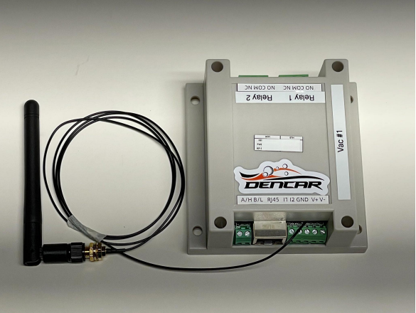
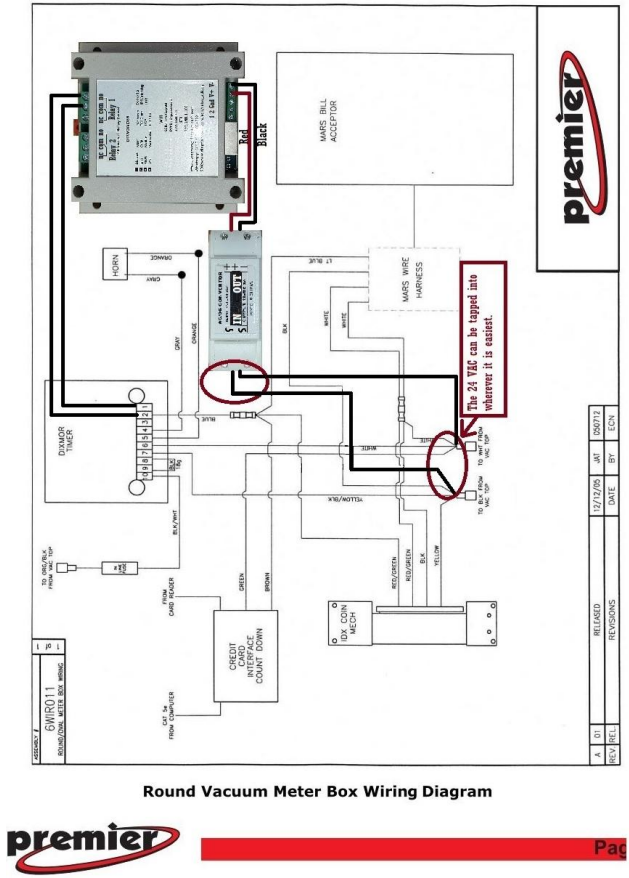
The relay will operate on voltage ranging from 12V to 24V AC or DC. Output relay 1 should be connected using the Normally Open (NO) and Common (COM) connections. Wire in parallel to the coin output in the equipment. The relay output contacts are dry contacts and can switch AC or DC up to 10 amps.
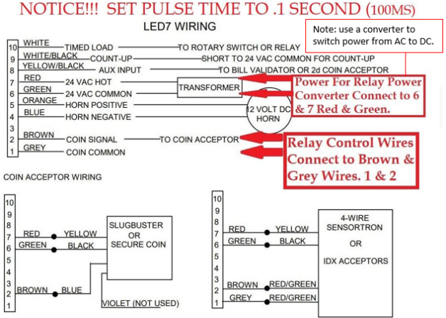
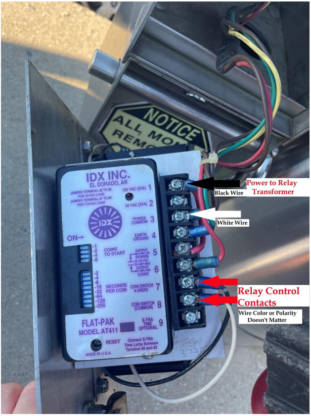
Sample wiring diagrams/pictures follow:
TROUBLESHOOTING WIFI-WIRED RELAYS
When troubleshooting the relay, there are 3 primary areas to consider: 1) network connection, 2) pulse configuration to the timer, and 3) wiring into the timer. The relay is designed to simulate a quarter pulse. When properly connected and configured, you should be able to insert a quarter into your coin mechanism and/or signal this relay and the result should be indistinguishable.
Network Connection
Good network connectivity is foundational for the relay to work. Start with the Control Console view. Log into the Site Controller and go to the Control Console view. You should see a solid red color indicator for the relay. If you see the color indicator flashing, this means the network performance is variable and the relay is losing connection to its application host on the site controller. Depending on the severity of the network performance, the relays will miss signals partially, variably, or completely. A solid network connection is vital to good performance of the relay.
When the relay is connected via a wired network connection, any variability in individual relay performance is likely caused by a physical wiring problem. Network terminations are the likely culprit followed by physical damage to the cable. Depending on the cable run, if network cables are run too close to electrical power runs, there can be interference from the power source. A shielded network cable can help mitigate interference if needed.
When the relay is connected via a WIFI connection, there are more variables to consider, so we must work to isolate the problem first, then mitigate. Signal strength is the most likely cause of a WIFI connected relay problem. Connect your phone to the Dencar WIFI network and stand next to the location where the WIFI relay is installed. Download the https://www.speedtest.net/ app for your phone and run a speed test while standing next to the WIFI relay install location. Record the results: a) download speed, b) upload speed, c) ping, d) jitter. Walk next to the network WIFI Access Point and re-run the same test. Compare the results. If there is significant variation in the test results, this indicates the signal strength of the WIFI signal is not sufficient at the install point. Proper network remediation needs to occur. If the network connection is good to the phone, we now know the exterior signal strength is good, and we need to troubleshoot the signal strength to the relay. Start by ensuring the WIFI antenna has a clear line of sight to the WIFI access point. The WIFI antenna must be mounted on the exterior of the device. The WIFI antenna can be mounted behind plastic, but if it is mounted behind or in metal, the odds of the connection being sufficient are slim. Start by placing the antenna outside the device completely and testing the relay performance. If you experience a properly performing relay with the antenna outside the device and performance issues follow after mounting the antenna inside the device, you now know the antenna needs to be moved. Keep in mind that the antenna cable could also be susceptible to power interference. When running the cable, keep it as far away from power lines as possible. Once you have the relay installed and the color indicators on the Control Console remain solid, you now know the network performance is good.
NOTE: Network performance can be impacted by other devices or components on the site differently during the day. This means if you perform the above testing at night when nobody else is on site, and the next day there are 20 people connected to WIFI all live streaming video, the performance will change. This is an extreme example, but the point is network performance is a point in time measurement. You will want to observe the Control Console during real world activity to ensure performance remains acceptable.
Pulse Configuration
The relay has 3 variables that can be configured. These are: 1) number of pulses sent, 2) pulse duration, and 3) pulse-to-pulse duration. These variables are set within the Customer Management Portal on the Site Controller component settings. When changes are made to these settings, the site controller must be restarted to download the changes.
The number of pulses sent is equivalent to how much money you want to simulate being deposited. If you have a $2 start on a vacuum, and you want a single scan to start the vacuum for the consumer, you would need to set the number of pulses to a minimum of 8 assuming the value of each pulse on your timer is $0.25. If your value is different, adjust accordingly.
Pulse duration is the amount of time that the signal is sending current from the relay to the timer. You will need to refer to your timer documentation to determine the exact required pulse duration. However, in general, newer electronic timers require a lower pulse duration value like 0.1 second. Older timers could easily accept a pulse duration of up to 1 second. The troubleshooting tip for pulse duration is to signal the relay and listen for the audible clicking of the relay. Count the audible clicks as you signal the relay. Assuming you hear the appropriate number of clicks (pulses), how did the timer respond? Is the timer loading some of the value or missing every pulse. An extreme example would be if you are sending a 1 second pulse and the timer misses every pulse, it is likely that the timer is designed to only accept a short pulse like .1 second. Contact your timer manufacturer if you don’t have documentation to determine the requirements. If the timer is responding to some of the pulses, but not all, the pulses may need a longer pulse-to-pulse duration.
Pulse-to-pulse duration is the amount of time delay between pulses. Since we are simulating quarter drops, it is easy to picture yourself standing at a device and inserting quarters into the device to get it to start. There is a delay time between how quickly you can insert quarters into the device. Older timers will have a higher requirement for time between pulses and newer electronic timers will have a lower requirement. Another extreme example would be setting your relay to send 8 pulses, with a pulse duration of .1 second and a .1 second pulse-to-pulse duration delay. The signal pattern would look like this: .1 on, .1 off, .1 on, .1 off, .1 on, .1 off, .1 on, .1 off, .1 on, .1 off, .1 on, .1 off, .1 on, .1 off, .1 on, .1 off. This means the entire transaction would only take 1.5 seconds. This may be appropriate for a newer electronic timer, but an older timer will likely miss some of these pulses because it is designed for a slower pulse rate. In this example, if you signaled 8 pulses, but the timer only accepted or posted value for some of the pulses, you would want to increase the pulse-to-pulse duration (delay).
Wiring into the Timer
Most timers are designed to accept pulses from multiple sources. For example, it is very common to see cash, coins, and credit card readers all pulsing a timer. The WIFI/WIRED RELAY is just another source sending pulses. When installing the relay, you want to connect to the same coin switch and coin common already in use. On the relay, connect relay 1 NO to the coin switch and relay 1 common to the coin common. If there are already multiple sources connected to these signal points, you are likely not reading this troubleshooting guide as this is just another source being added and everything is working.
If you are reading this guide as a result of erratic behavior when the relay sends pulses, there
are likely 1 of 2 scenarios. Scenario 1 is just a simple miswire. To correct, review to ensure your
power source is correct (the WIFI/WIRED RELAY requires a 12-24VDC power source) and the
relay 1 wiring on the relay is properly connected. Ensure all wiring is snug. A loose wire can
send you down a rabbit hole of investigating every other variable. Scenario 2 comes into play if
you are wiring into a multi-unit (i.e. a combination vacuum/fragrance machine). You may need
to add wiring or bypass wiring or may only be able to activate a single function easily. If there
are timer controls that change the value of the inputs, or variable selections that require
different inputs, you will need to map out the wiring to ensure you connect to the proper coin
inputs. Without a wiring diagram, you will need to identify where each payment source is
wired, and wire to the source you want to mimic. We do not currently have good pictures or
diagrams of these set-ups. If you would like to diagram your setup, we would be happy to
review and plan your wiring with you.